
What is Adas?
Advanced Driver Assistance Systems (ADAS) were created to make driving safer and better control driving.
In other words, it is to prevent car accidents and prevent deaths and injuries by reducing their serious effects.
ADAS was created to automate vehicle systems, adapt it to the vehicle, and improve the system.
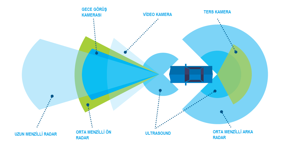
- Systems Contained by ADAS
- Pedestrian detection and avoidance
- Lane departure warning and vehicle correction
- Traffic sign recognition
- Automatic emergency braking
- Blind spot detection
Adas' life-saving systems combine interface standards and generate multi-view based algorithms by supporting real-time multimedia, image processing and sensor fusion subsystems.
How is Autel Adas Calibration done?
- Autel device connects to vehicle
- The vehicle's ignition is turned on.
- Automatic "VIN" is used to connect to the vehicle.
- Vehicle model and equipment are verified
- Enter the Adas menu.
- Task calibration is selected and continued by selecting the integrated driver support system calibration.
- The calibration frame is brought in front of the vehicle.
- The vehicle must be on a flat surface.
- The pattern card and target board holder should not be attached to the frame.
- To make correct alignment, the adjusting bolt must be turned to correct data.
- The arm is loosened and the scale value is set to zero.
- The arm is tightened to fix the rod.
- The pointer aligns with the 0 marked line on the slide plate and the bolt is tightened to open the slide plate.
- Lasers and beams in the front center of the vehicle are targeted and bar height adjusted
- The frame is moved slowly towards the vehicle.
- The vehicle centerline of the impeller should be 411 millimeters.
- Laser focuses on the very center of the front of the vehicle.
- When the button is in the closed position, the bolts on the base are turned slowly until the laser is fixed to the ground.
- The two wheel clamps are attached to the rear wheels and their claws are placed outside the wheel rim
- Make sure that the wheel clamps are securely fastened to the wheels.
- The connecting shaft of the laser is placed in the clamp port.
- Laser calibration part is attached to the vehicle and fixed by tightening.
- The attached lasers are turned on and the beam is adjusted to illuminate the rulers on either side of the top cover plate.
- The handle is loosened and the fine adjustment bolt is turned until the rulers on either side of the crossbar plate reach the correct figures
- Laser-illuminated cross bar is fixed by tightening to achieve the same value.
- Caps at both ends of the connecting rod are removed
- The wheel lasers are adjusted to control the up and down movements of the reflected beam.
- Laser boards should glow on one of the scale boards
- The bolt can be rotated to the left or right side until the scale values lit by the reflected beam are the same on both sides of the beam.
- The calibration frame is parallel to the vehicle and the covers on the connecting rod are closed.
- Wheel clamps are removed from the vehicle.
- The Ribbon Camera Calibration is started.
- The sliding plate bolts on the cross section of the target board holder are tightened, and the target board holder is attached to the cross bar and tightened.
- To fix the bolts to the handle, each of the two target board sliders is brought to 640 millimeters on the ruler attached to the handle.
- Slip tightened
- The output of the target board is set up on CSC 601 slash 8L
- Left handle and attached target CSC 601 slash connect on right installed holder
- The left and right cards are different in the right card holder slider.
- Re-checks are made to make sure that the targets are placed correctly.
- Windows and lighting fixtures, reflective material and black and white pattern material similar to the calibration card on the back of target cards
- All screws on the bottom of the calibration frame are rotated and by looking at the bubble level to make sure the frame is level.
- The ruler is loosened
- The pointer is adjusted by raising the cross bar to reach a certain height value.
- For this calibration, the pointer on the B side of the ruler should be set to 1500 millimeters.
- Continue by pressing the OK button on our tablet and continue to follow the directions.
- The ruler is fixed by returning to its original position
- Continue by touching the strip camera calibration button on the tablet.
- When the device completes the process, it will give you a successful warning and the process will be completed.
If you want to get more information about ADAS Calibration system;
You can reach us by calling 0850 755 02 30 or at https://nitrobilisim.com.tr/tr.