Tuesday, April 7, 2020
Honda Tracking Camera Calibration Process with Autel Maxisys Adas
Honda Lane Tracking Camera Calibration Process with Autel Maxisys Adas
Known as a variant of the series, the MaxiSYS Adas tablet provides a comprehensive Adas Calibration with advanced diagnostic capabilities and time-saving fast service features. What is required is a strip camera calibration.
INTEGRATED DRIVER SUPPORT MODULE CALIBRATION PROCEDURE FOR BAND CHANGE CAMERA
In equipped Honda vehicles, these process preparations vary depending on the vehicle and system.
- To ensure precise calibration, plug the VCI into the vehicle and turn on the ignition.
- Ignition on, engine off.
- Connect the device to the vehicle, tap the auto VIN button in the upper left corner of the screen to read the vehicle.
- Identify the ID number, vehicle model, and equipped systems.
- Choose a task calibration and then choose integrated driver support system calibration.
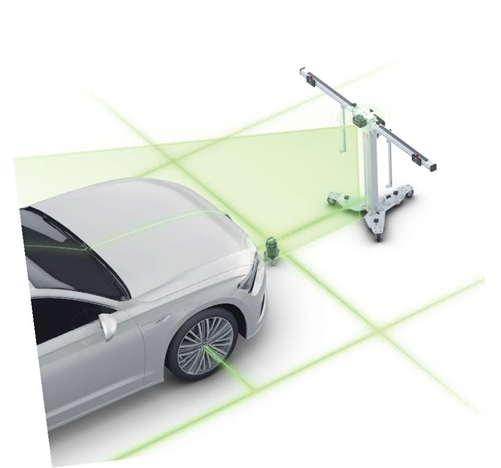
- Bring the calibration frame to the front of the vehicle.
- The floor must be level.
- Neither the pattern card nor the target board holder should be attached to the frame. Turn the fine adjustment bolt for alignment.
- Loosen the lever and turn the fine adjustment bolt until the scale value is zero.
- Tighten the handle to secure the crossbar.
- Align the pointer with the line marked 0 on the slide plate and tighten the bolt to open the slide plate.
- Aim the lasers and the beams in the front center of the vehicle, adjust the height of the rod.
- Slowly move the frame the distance between the back of the cross bar.
- The impeller's vehicle centerline should be 411 millimeters.
- Focus the laser on the center of the front of the vehicle.
- With the frame in the closed position, rotate the bolts in the base not too tight until the laser is fixed to the ground.
- Attach the two wheel clamps to the rear wheels and place the claws on the outside of the wheel rim.
- Make sure the wheel clamps are securely fastened to the wheels.
- Insert the connecting rod of the laser into the clamp port.
- The laser calibration board should be on the front of the vehicle.
- Fix the laser by squeezing it.
- Turn on the attached lasers and adjust them to illuminate the rulers on either side of the beam top cover plate.
- Loosen the handle and turn the fine adjustment bolt until the rulers on both sides of the crossbar plate rotate.
- Tighten the handle to fix the laser illuminated crossbar of the same value.
- Lift the cover plates at both ends of the connecting rod.
- Adjust the wheel lasers to control the up and down movement of the reflected beam. The reflected beam should shine on one of the scale boards of the laser boards.
- Rotate the bolt left or right until the scale values lit by the reflected beam are the same on both sides of the beam.
- Now the calibration frame is parallel to the vehicle, close the cover plates on the connecting rod.
- Remove wheel clamps and clamps from wheels
STARTING THE STRIP CAMERA CALIBRATION
- Tighten the slide plate bolts at the cross section of the target board holder.
- Attach the target board holder to the cross bar and tighten.
- Move each of the two target board sliders to 640 millimeters on the ruler attached to the handle to secure the bolts to the handle.
- Then tighten the sliders in place.
- The left handle and attached target CSC 601 slash are on the right board holder, while the exit target board CSC 601 is installed on the slash 8L.
- Left and right cards are different in the right card holder slider.
- Make sure that the targets are placed correctly and there should be no light sources.
- Reflective material and black and white pattern material, which do not have windows or lighting fixtures, are similar to the calibration card on the back of the target cards.
- Turn all the bolts on the base of the calibration frame.
- Make sure the frame is straight by looking at the bubble level
- Loosen the ruler to touch the ground.
- Adjust the height of the crossbar to set the pointer to a specific height value.
- For this calibration, the pointer on the B side of the ruler must be set to 1500 millimeters.
- Push the ruler back to its original position and fix it.
- The tablet will show the message "Passed" when the ribbon changes the camera calibration.
