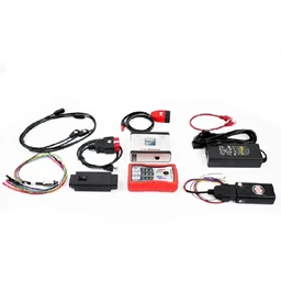
Ecutest Ecu Test Simulator Description
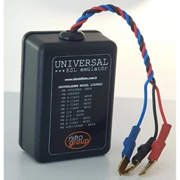
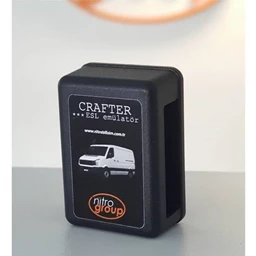
The purpose of the Ecutest device; In the event that the electronic control units (ECU) used in the engines of the cars, fail, to repair the control unit in an original way without damaging any parameters on the vehicle, to reduce the repair costs and to test the control units without a vehicle on the table.
Nitro Mekatronik company is developing rapidly in parallel with the developments in information technologies, vehicle software and hardware technologies.
In worldwide, ECU PROGRAMMING processes has begun more practical to interpret, develop, test and repair the ECU without disassembling.
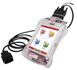
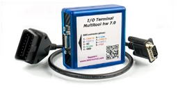
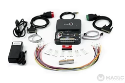
After opening ECU TEST device, thanks to the universal and brand-specific sockets, test is provided with completely online software without opening the ECU.
These stages will be as follows:
- All vehicle-specific parameters are loaded during the ECU selection and the required information is automatically loaded by a server.
- Scheme and diagram of the socket, thanks to the database (created by Nitro Mekatronik) installed in the ECU server selected by the application; will be shown thanks to photos and videos
After connection, the ECU will reflect the voltages, injectors, sensor and valve outputs to the screen.
- If there is an error in the ECU, the incorrect section will be displayed in red.
- When the ECU is repaired and the error is corrected, the red color will automatically appear on the screen.
- The simulated ECU will provide an environment as if working on the car and will operate on all moving sensors and parameters thanks to the button placed as a gas pedal. Thanks to this, live values in the ECU can be seen with the ECU-Tester.
- Engine Control Unit and immobilizer, body, indicator, ABS etc. matches can be checked.
- Instead of replacing the control units of the vehicles, we repair and recycle them.
- Sensor input and output information, voltage values, required values, measured values of the ECU
Tester can be displayed. We aim to make the necessary analysis and triggers by sending a signal to the control unit through the device with the simulator.
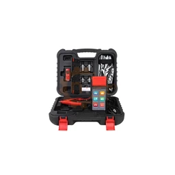
This device, which Nitro Mekatronik’s engineers are working diligently, will give you a new perspective in fault detection and simulation. If you want to access this privilege, you can purchase from the product page
Hardware Specifications
- 8 Injectors High and Low Voltage Simulation (Max 35V)
- 8 Coil Simulation Input Lines We Can Read 8 Voltages (Max 35V)
- 28 Sensor Output Simulation (Max 12V)
- 16 Digital Actuator (Valve) Outputs
- 4 PWM Inputs (10 Hz – 10 kHz)
- 4 PWM Output (1Hz – 20kHz)
- 4 H Bridge (Motor in) Inlet (Frequency, dutycircle)
- 2 Inductive Outputs (Crank and Cam)
- 4 Hall Effect Sensors (Crank and Cam, 5v and 12V options available)
- 4 Relays 2 CAN-BUS Line (CAN1-CAN2)
- 1 K-Line Line 1L-Line Line (J1708, J1850)
- 2 Power Supply Outputs (One voltage and current variable, one fixed)
- 1 OBD Output Indicator, Immo Antenna and BCM Support Protection Against High Voltage, Current, All Grills and Outputs
- 3.2 Inch TFT Screen 120 Ohm Canbus Filter Circuit
Software features
- Working Online
- High Speed Communication Technology Between Computer and Device
- Modern User Friendly Software
- ECU Internal Schema Support
- ECU Pin Output Scheme Support
- ECU Socket Guide Numbered For Easy Operation

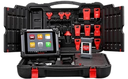
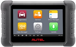
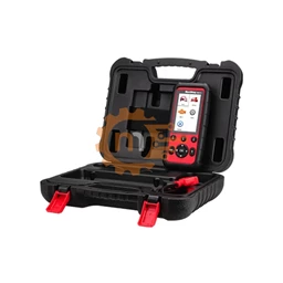
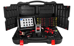


.webp?size=256)



 Cihazı.webp?size=256)
