

CAN Bus Diagnosis and ECU Fault Analysis in ECU Repair
Today's vehicle technology is equipped not only with mechanical parts but with electronic systems that manage, monitor, detect faults, report them to the driver, and store them in memory. At the center of these systems is the ECU (Electronic Control Unit), commonly known as the vehicle brain, and the CAN Bus (Controller Area Network) system that enables communication between these ECUs plays a vital role.
With technology’s influence today, when a vehicle breaks down, you need to listen to the CAN bus rather than simply opening the hood. This shift has transformed the professional perspective of both service technicians and engineers. In this blog, we explain ECU structure, CAN Bus diagnosis processes, and how these structures are analyzed and interpreted in clear technical language.
What Is an ECU and What Does It Do on a Vehicle?
The ECU, or Electronic Control Unit, is an electronic board that manages a specific system in a vehicle. That system may be the engine, the transmission, or even the windshield wipers. Low-segment base-package vehicles may have 6–7 ECUs, while fully equipped upper-segment vehicles may have 70–80 ECUs.
Each ECU receives data from sensors, processes it, and sends signals to actuators so the system operates. For example, when the accelerator pedal is pressed, the engine ECU adjusts the air-fuel mixture and sends an injection command to the injectors.
ECUs appear independent but all work in connection with each other. The system that enables ECUs to work together is called the CAN Bus system. ECUs continuously exchange data over the CAN line. In the CAN-Bus system, hundreds or even thousands of messages are transmitted in milliseconds. These messages are continuously read by other control units so other systems can be analyzed, commands can be sent to actuators according to jointly operating systems, and faults can be detected in real time.
How Does the CAN Bus System Work?
CAN Bus is a protocol structure that provides nearly instant and reliable data transmission between different ECUs. In this system, messages are sent with an ID. This ID identifies which system the message comes from and which system it belongs to. The message structure includes DLC (message length) and data fields.
Messages are processed as follows:
• Sensor data such as engine coolant temperature, accelerator pedal position, and brake pressure are continuously transmitted to the ECU.
• The ECU continuously monitors this data and instantly sends it to other ECUs as messages over the CAN-Bus line.
• For example, the Engine Control Unit continuously sends “vehicle speed” information to the Transmission Control Unit.
• The Transmission Control Unit decides to shift to the appropriate gear based on this information.
This message traffic plays a major role in communication among control units. A technician who can analyze the CAN line correctly can understand not only the fault but also why and when it occurred.
Fault Diagnosis with CAN-Bus Analysis
Many repair technicians, when they hear diagnostic tool, read fault codes with an OBD2 device and replace the part described in the fault code explanation. However, this method is superficial and does not always reveal the true cause. Real fault diagnosis begins by interpreting DTC (Diagnostic Trouble Code) fault codes, but that alone is not always enough.
In modern vehicle systems:
• Freeze frame (frozen instant vehicle data recorded at the moment the fault occurred) can be read.
• Values such as engine speed, coolant temperature, and accelerator pedal position sensor at the moment the fault occurred can be analyzed.
• These data are very important for finding the true cause of the fault.
For example, when you encounter a “rich fuel mixture” fault, directly replacing the oxygen sensor may not be the solution. Perhaps an injector is faulty, perhaps there is an air leak in the intake or turbo system, perhaps the MAF sensor is sending incorrect information. If freeze frame is checked, causes of such faults can be revealed.
Communicating with the ECU via UDS Protocol
It is possible to communicate with control units in vehicles not only by listening and analyzing but also by sending messages. This communication can be performed using the UDS (Unified Diagnostic Services) protocol. UDS is a comprehensive protocol used worldwide, based on the ISO 14229 standard, that enables fault diagnosis, testing, and calibration with the ECU.
Starting a Diagnostic Session
To work in depth with an ECU, a diagnostic session must first be started. A diagnostic session is started with the 0x10 service command. Session types are listed below.
• DefaultSession (0x01): Used only for basic DTC (fault code) queries.
• ExtendedSession (0x03): Used for live data queries and special tests.
• ProgrammingSession (0x02): Used for software-related critical operations.
These sessions provide access to the security levels of the ECU you want to communicate with. You cannot query the ECU directly or start any communication without entering this session.
Security Access
To enter some sessions or write information to the ECU, the ECU’s authorization system requires the correct access code. This is performed only by starting the “SecurityAccess” service with code 0x27.
This service works on a challenge-response basis.
1. The ECU gives you a code called seed.
2. Your device or your algorithm calculates the “key” corresponding to this seed.
3. If the key message sent to the ECU is correct, access opens and you can begin intervening in the ECU.
Security access is very important for those developing manufacturer-level diagnostic software. Because many services work only when this access is granted.
Reading Sensor Data
Service code 0x22 lets you query Live Data information from a control unit. With this service, you can reach instant values of all sensors and actuators connected to the control unit:
• Engine coolant temperature
• Throttle position sensor
• High or low fuel pressure
• Oxygen (Lambda) sensor value
• EGR valve opening position
What can you do with these values?
• Understand the true causes of faults,
• Determine whether calibration is correct,
• Create real-time sensor or actuator data graphs.
With devices such as KaanAnalyzer, you can monitor and record this data in continuous flow.
KaanAnalyzer Standout Features
- ✓ Real-time dual-channel CAN data analysis
- ✓ UDS protocol support
- ✓ Diagnostic session playback feature
- ✓ Advanced ECU security access
- ✓ Multi-platform support
Calibration and Data Writing
Control units used in vehicles today do not only provide sensor and actuator values. With proper authorization and the correct session started, new parameters can also be added. This is done by sending service code 0x2E to the ECU. For example:
• EGR opening min-max range
• Turbo boost min-max limit value
• Fuel injection timing and similar parameters can be written to the control unit
This service is frequently used during ECU calibration or remapping operations. Vehicle manufacturers or engineers can customize systems with this service and write values suitable for the vehicle from R&D results to the control unit.
This operation requires great care and knowledge. Any incorrectly written value can damage the engine or disrupt engine operation. Therefore, before performing the operation, an ECU backup must absolutely be taken with devices such as Flex produced by MagicMotorSport.
Active Test Services
Some active tests can be triggered on the ECU. This is important for fault resolution. For example:
• If you want to test the radiator cooling fan, service 0x31 can be used to run the fan.
• Fuel pump test, A/C relay test, wastegate actuation test, EGR valve movement test, and similar operations can also be performed with this service.
Using this service, you can perform tests over CAN-Bus without physical intervention on the vehicle.
DTC (Fault Code) Clearing
Clearing fault codes is used when the vehicle first arrives at the workshop to understand whether the fault is temporary or permanent. Afterwards, fault codes are cleared after the fault is fixed. When a DTC clear command is sent:
• All fault codes recorded by the control unit, temporary and permanent, are cleared.
• Freeze frame data is completely deleted.
• All fault history records are deleted.
We recommend performing fault code clearing only after the system is fully repaired.
Freeze Frame Data (Sensor and Actuator Data at the Moment of Fault)
When a fault occurs, control units store the sensor and actuator status of the system at that moment in memory. This information is stored in ECU memory as “freeze frame.” It may include:
• Vehicle speed
• Engine speed
• Accelerator pedal sensor position
• Engine or other temperature values
• Battery or sensor voltage conditions
Because freeze frame records the conditions under which the fault occurred, it helps you understand the fault more clearly.
Real-Time CAN-BUS Data Monitoring (Live Data)
When performing fault diagnosis on control units or CAN-Bus analysis, access to instant data flow as well as historical data provides a major advantage in detecting faults. Hundreds or even thousands of messages flow on the CAN Bus line every second. Each message carries information about vehicle sensor data, actuator data, driver inputs (pedals, steering movement, gear), and environmental conditions.
With real-time data (Live Data) monitoring:
• Communication between ECUs can be observed instantly,
• Sensor and actuator values can be viewed instantly,
• Suspicious CAN data (missing when expected, or arriving differently than expected) can be detected.
During this process, the KaanAnalyzer device works as a listener and receives messages instantly without harming the CAN line.
CAN ID Filtering and Message Extraction
CAN communication is generally very fast and complex. Seeing all messages at once can make analysis difficult. That is why filtering is used on the KaanAnalyzer device. Every CAN message has an ID, and these IDs can be filtered. With filtering, the following can be done:
• Messages belonging to a specific control unit can be monitored,
• Messages belonging to specific functions (for example: Engine, Airbag, Transmission) can be separated,
• Messages of the desired system can be analyzed clearly.
For example, ID 0x7E0 is the engine control unit ID. By filtering this ID, you can observe only engine-related messages.
Real-Time Graphs and Signal Decoding
Advanced devices such as KaanAnalyzer can display message data not only as raw CAN bus values but also graphically. For example:
• Accelerator pedal position can be shown as a percentage,
• Speed information can be shown as a timeline,
• Engine coolant temperature can be shown as a graph.
Log File Recording
Recording values is as important as instant analysis and reviewing them later. By starting log recording, you can record CAN-Bus values.
Log records are especially useful in the process of detecting recurring faults with uncertain timing, evaluating test drives, and software development processes.
Playback Feature
Resending CAN messages from a recorded log file is also possible with KaanAnalyzer. A previously recorded CAN log file can be sent again to the CAN line. This way you can trigger an ECU’s behavior again or create simulations to test your products.
This feature can be used especially in R&D processes, ECU software development and testing, and creating virtual diagnostic environments during training.
For example, a vehicle’s engine acceleration can be recorded as a log and then sent again as playback in simulation for checks.
Making Sense of the Data
The most important stage of real-time CAN monitoring is interpreting CAN messages.
KaanAnalyzer vs Standard OBD Devices
| Features | KaanAnalyzer | Standard OBD Devices |
|---|---|---|
| Real-time CAN data monitoring | ✓ | ✗ |
| ECU simulation | ✓ | ✗ |
| UDS Protocol | ✓ | ✗ |
Service technicians with devices such as KaanAnalyzer can connect to ECUs and examine all systems in detail, interpret fault codes, analyze supporting sensor data, and make definitive diagnoses by matching customer complaints with technical data.
Using such systems in workshops provides major advantages for accurate fault detection, correct intervention, and definitive repair.
R&D Engineers and Calibration Centers
To develop, produce, or test an ECU, buying software alone is not enough. You also need to see the hardware’s response on a real vehicle. With CAN analysis systems such as KaanAnalyzer
• All ECU messages can be monitored instantly
• Test scenarios can be created and system performance measured
• Accuracy of calibration values can be analyzed
• Values of different software versions can be compared.
Academics and Students
CAN analysis devices can also be used in universities, vocational schools, and training institutions. Especially in final projects (for example autonomous vehicle control), theses (for example developing CAN-based diagnostic systems), and laboratory applications (for example ECU simulation), these devices in academia allow students to move theoretical knowledge into practical knowledge.
Software Developers
For teams developing software that can read data over CAN, these devices are raw data sources. Analysis devices enable real-time testing. They provide the ability to create ECU simulations and play CAN scenarios. In addition, with systems integrated on platforms such as Python, C++, and Qt, developers can build test automation and simulation infrastructure.
CAN-Bus Fault Diagnosis Process
Contributions that professional analysis devices such as KaanAnalyzer provide to CAN-Bus fault diagnosis processes include:
Resolving U-coded faults
Diagnosing CAN-Bus-related faults of control units that cannot be communicated with
Diagnosing incorrectly coded gateway faults
Diagnosing broken CAN-Bus lines
Diagnosing short-circuit CAN-Bus communication faults
Devices used in CAN-Bus analysis systems must also be more than ordinary. Because products that not only connect but also interpret data are needed.
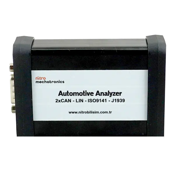
KaanAnalyzer, unlike an OBD device, can analyze real-time dual-channel CAN data, send instant commands to ECUs with the UDS protocol, record CAN messages and replay them as a diagnostic session (playback), perform professional-level diagnosis with ECUs through security access, and be used on many platforms including automotive, agricultural vehicles, and heavy-duty vehicles. With these features, KaanAnalyzer is offered to users as a universal device for R&D, vehicle services, and training.
Transform Your Automotive Diagnosis Processes with KaanAnalyzer
In modern vehicle technologies, staying ahead is possible with the right equipment. With KaanAnalyzer CAN Bus Analysis Device you can access ECU data and diagnose faults with their true causes.
BUY NOWFinding faults in the automotive sector used to be a matter of craftsmanship; today faults cannot be resolved without examining digital data. Vehicles are becoming more digital every year. Services, technicians, engineers, and training institutions that cannot keep up with this transformation fall behind technology.
Devices such as KaanAnalyzer are offered to you as one of the most practical and powerful ways to adapt to this change.
Video Explanation
Our ECU simulation work over CAN-Bus: