

What Is ADAS?
Advanced Driver Assistance Systems (ADAS) were created to make driving safer and give the driver better control — preventing accidents and reducing serious impacts, deaths and injuries.
ADAS was developed to automate vehicle systems, adapt them to the vehicle and improve the system.
Systems Included in ADAS
- Pedestrian detection and avoidance
- Lane departure warning and lane keeping
- Traffic sign recognition
- Automatic emergency braking
- Blind spot detection
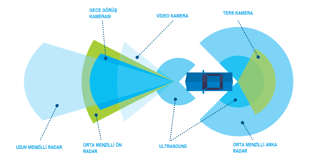
ADAS life-saving systems combine interface standards and support real-time multimedia, image processing and sensor fusion subsystems to produce multi-view algorithms.
How Is the Autel ADAS Calibration Procedure Done?
- Connect the Autel device to the vehicle
- Switch the ignition on
- Use automatic VIN to connect to the vehicle
- Verify vehicle model and equipment
- Enter the ADAS menu
- Select task calibration and continue with integrated driver assistance system calibration
- Place the calibration frame in front of the vehicle
- The vehicle must be on level ground
- Pattern card and target board holder must not be attached to the frame yet
- Turn the adjustment bolt for correct alignment
- Loosen the arm and set the scale value to zero
- Tighten the arm to lock the rod
- Align the pointer with the 0 line on the sliding plate and tighten the bolt
- Target lasers and front centre beams; adjust rod height
- Move the frame slowly toward the vehicle
- Vehicle centre line on the wheel must be 411 mm
- Focus the laser on the exact centre of the vehicle front
- With the button off, rotate base bolts until the laser is fixed to the ground
- Attach two wheel clamps to the rear wheels
- Ensure wheel clamps are firmly fixed
- Insert the laser connection rod into the clamp port
- Attach and tighten the laser calibration part to the vehicle
- Open attached lasers and adjust to illuminate scales on both sides of the top cover plate
- Loosen the handle and turn the fine adjustment bolt until crossbar scales reach the correct values
- Tighten the crossbar illuminated by the laser to lock the same value
- Remove caps at both ends of the connection rod
- Adjust wheel lasers to check reflected light movement
- Laser panels must light on one of the scale boards
- Rotate the bolt until scale values lit by the reflected beam match on both sides of the beam
- Calibration frame is parallel to the vehicle; close caps on the connection rod
- Remove wheel clamps from the vehicle
- Proceed to lane camera calibration start
- Tighten sliding plate bolts on the cross member of the target board holder and attach to the crossbar
- Set each target board slider on the holder ruler to 640 mm and tighten
- Mount target board output on CSC 601 oblique line 8L
- Connect left holder and attached target CSC 601 oblique line to right mounted holder
- Left and right cards differ on the right card holder slider
- Recheck that targets are placed correctly
- Windows, lighting, reflective and black-white pattern material resemble the calibration card behind target cards
- Rotate all screws on the calibration frame base and check bubble level
- Loosen the ruler
- Raise the crossbar to bring the pointer to the specified height
- For this calibration, set the pointer on side B of the ruler to 1500 mm
- Press OK on the tablet and follow the instructions
- Return the ruler to original position and lock it
- Tap lane camera calibration on the tablet to continue
- When the device completes the procedure it shows success and the process is finished
For more information about Jaltest ADAS use click here
For detailed information, please call us:
0850 755 02 30
Related Products

Autel
Autel Tesla 3 Tesla Y Bağlantı Cable
Autel'in Tesla 3 ve Y modellerine özel tasarladığı bağlantı kablosu, araç içi veri okumayı ve hata kodlarını silmeyi mümkün kılar. Özellikle Autel Ultra serisi…
$59.00 +VAT

Autel
Autel MaxiCheck MX900BT Diagnostic & TPMS Scan Tool
Autel MX900BT is an 8" touchscreen professional diagnostic tablet with full-system diagnostics, bi-directional control, 40+ service functions and full TPMS sup…
Stokta, Kargoya Hazır
Call for pricing

Autel
Autel IA900WA Wheel Alignment & ADAS Calibration Frame
Stationary Autel calibration frame combining wheel alignment and ADAS calibration in one station. Six cameras, 24" touchscreen, robotic frame movement.
Call for pricing


