

Autel Maxisys Adas Honda Lane Tracking Camera Calibration Procedure
Known as a variant of the Autel series, the MaxiSYS Adas tablet provides comprehensive ADAS calibration with advanced diagnostic capabilities and time-saving quick service features.What is required is a lane camera calibration.
INTEGRATED DRIVER SUPPORT MODULE LANE CAMERA CALIBRATION PROCEDURE
On equipped Honda vehicles, preparation for this procedure varies by vehicle and system.
- Connect the VCI to the vehicle and turn the ignition on for precise calibration.
- Ignition on, engine off.
- Connect the device to the vehicle and tap the automatic VIN button in the top left of the screen to read the vehicle.
- Identify the VIN, vehicle model, and equipped systems.
- Select a task calibration, then select integrated driver support system calibration.
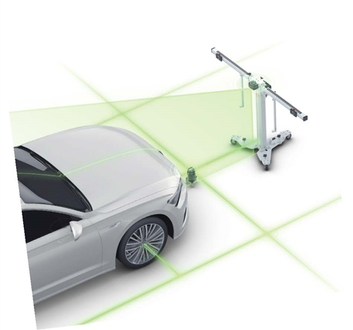
- Place the calibration frame in front of the vehicle.
- The floor must be level.
- Neither the pattern card nor the target board holder should be attached to the frame. Turn the fine-adjustment bolt for alignment.
- Release the lever and turn the fine-adjustment bolt until the scale value is zero.
- Tighten the lever to lock the crossbar.
- Align the pointer with the zero-marked line on the sliding plate and tighten the bolt to lock the sliding plate.
- Target the lasers at the front center beams of the vehicle and adjust the bar height.
- Slowly move the frame to adjust the distance behind the crossbar.
- The vehicle center line on the wheel should be 411 millimeters.
- Focus the laser on the center of the front of the vehicle.
- With the frame in the closed position, turn the base bolts without over-tightening until the laser is fixed to the ground.
- Attach two wheel clamps to the rear wheels and place the claws outside the wheel rim.
- Ensure the wheel clamps are firmly fixed to the wheels.
- Insert the laser connection pin into the clamp port.
- The laser calibration board should face the front of the vehicle.
- Lock the laser by tightening.
- Turn on the attached lasers and adjust them to illuminate the scales on both sides of the beam top cover plate.
- Release the handle and turn the fine-adjustment bolt until the scales on both sides of the crossbar plate rotate.
- Tighten the lever to lock the crossbar at the same value illuminated by the laser.
- Remove the cover plates at both ends of the connection bar.
- Adjust the wheel lasers to check the up and down movement of the reflected light. The reflected beam should shine on one of the scale panels on the laser boards.
- Turn the bolt left or right until the scale values lit by the reflected beam are equal on both sides of the beam.
- The calibration frame is now parallel to the vehicle; close the cover plates on the connection bar.
- Remove the wheel clamps and clamps from the wheels.
STARTING LANE CAMERA CALIBRATION
- Tighten the sliding plate bolts on the cross section of the target board holder.
- Attach the target board holder to the crossbar and tighten.
- Move each of the two target board sliders to 640 millimeters on the ruler attached to the holder to fix the bolts to the holder.
- Then tighten the sliders in place.
- While the output target board CSC 601 diagonal line 8 L is mounted on the left holder, the attached target CSC 601 diagonal line right is on the right holder.
- Left and right cards differ on the right card holder slider.
- Ensure targets are placed correctly; there should be no light source.
- No windows or lighting fixtures; use non-reflective material and black-and-white pattern material similar to the calibration card behind the target cards.
- Turn all bolts on the base of the calibration frame.
- Check the bubble level to ensure the frame is level.
- Loosen the ruler to touch the ground.
- Adjust the crossbar height to set the pointer to a specific height value.
- For this calibration, the pointer on side B of the ruler should be set to 1500 millimeters.
- Push the ruler back to its original position and lock it.
- When lane camera calibration is completed, the tablet will display a "Successful" message.
For detailed information, please call us;
0850 755 02 30
Related Products

Autel
Autel Tesla 3 Tesla Y Bağlantı Cable
Autel'in Tesla 3 ve Y modellerine özel tasarladığı bağlantı kablosu, araç içi veri okumayı ve hata kodlarını silmeyi mümkün kılar. Özellikle Autel Ultra serisi…
$59.00 +VAT

Autel
Autel MaxiCheck MX900BT Diagnostic & TPMS Scan Tool
Autel MX900BT is an 8" touchscreen professional diagnostic tablet with full-system diagnostics, bi-directional control, 40+ service functions and full TPMS sup…
Stokta, Kargoya Hazır
Call for pricing

Autel
Autel IA900WA Wheel Alignment & ADAS Calibration Frame
Stationary Autel calibration frame combining wheel alignment and ADAS calibration in one station. Six cameras, 24" touchscreen, robotic frame movement.
Call for pricing


